Modular, laser-cut MDF sculpture with Python and DXF
27 Mar 2011
TechnologyOriginally posted at https://tech.labs.oliverwyman.com/blog/2011/03/27/modular-laser-cut-mdf-sculpture-with-python-and-dxf/
This month’s post is something a little bit different to the usual LShift posts. Don’t worry, there’s still plenty of software and algorithms in there, but I’m also creating an actual physical object as well (shock horror).
I’ve recently acquired access to a laser-cutter, and I’ve been going through a bit of a learning process and seeing what I can do with it. Like everyone else, I started with other people’s designs, but I’d been thinking about doing something of my own. Along the way, I’d found and used the BoxMaker which is a very useful service for generating laser-cutter plans to make a cube of arbitrary size, and this got me thinking. I wanted to do more advanced things with multiple cubes, but designing all the joints correctly by hand would be an exercise in frustration. Enter the imaginatively named cube generator
The core idea is pretty simple: provide the cutting plans for a sculpture made out of a collection of cubes. Also, along the way I’ve also ended up generating a 3D version to allow me to double-check the results and some instructions on how to build the cut pieces into the final sculpture.
Input to this is a simple file consisting of a series of ‘’ and ‘-‘ characters representing cubes and gaps. For example, this is the specification for a level-1 Menger sponge. Each collection of * and – is one layer, and layers are separated by empty lines. The grid for a single cube is in fact just a ‘’ on it’s own with no other content.
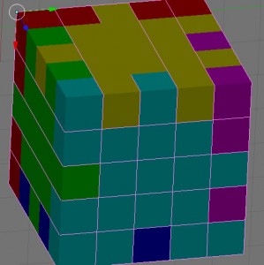
Given that, we can start constructing the pieces. First off, we construct the “degenerate” cubes, by temporarily ignoring the problem that two bits of the end MDF can’t occupy the same physical space. To aid the output later on, we actually store it in two different ways – as a 3d grid of cubes and a series of faces that will be cut out from the laser-cutter. Each cube is 1 unit3, with the unit length defined as the depth of the material (3mm in my case). For the simple “one cube” case, we’ve now got 6 square faces, and the 3d space has some cubes with multiple “owners”. An owner is defined as a face of the eventual structure that needs that cube to exist so that face actually works in the end structure, so in the “one cube” case all of the edges have 2 owners, and the corner unit cubes each have 3 owners (as they’re the intersection of 3 faces). Similar things apply for more complex structures, with up to 6 owners in some cases, but the same principles apply.
We’ll get onto improving that situation in a little bit (as the eventual output needs each cube to only have a single owner, or it won’t fit together), but first we need to do some culling of faces. In the “one cube” case, this isn’t necessary as all of the faces are external faces of the end structure, but for more complex structures this needs to be done. In short, an external face is one that’s either next to a border of the 3d space in which the structure as a whole is defined, or it needs to have a clear path to an empty space. If we take a simple “two cubes joined together” case, we can see that the two faces that are joined together aren’t actually needed for the end sculpture, as they can’t be seen from the outside, and so we can discard them entirely and still get the same end shape.
So, we’re down to just external faces. We’ve still got a degenerate structure, but all of the unit cubes with multiple owners should be confined to the outside edges of faces, so we can now proceed to construct jigsaw-puzzle style pieces to make the structure. We start with the 2-owner cases (i.e. edges). These can all be solved by finding the pairs of owners and giving one cube at a time to each possible owner, creating a “crenellated”-style sequence of interlocking notches. Once that has been done we can proceed to the 3+-owner cubes (i.e. corners). In each case, at least one of the owners should be a single-owner of one of the neighbouring cubes by now (I don’t have a full proof of this, but it seems to be true so far), so we pick one of those at random. We only use the non-diagonal neighbours here, because then whichever random neighbour we picked will be able to connect it’s single-owner neighbour edge cube to the corner cube.
At this point, we’ve got enough to start outputting viable cutting plans. I’m using a further-modified version of the SDXF library for Python. DXF has the nice property that it can be used for both 2-D and 3-D plans, so I can output both the laser-cutter plans and a file that can be read by Blender so I can double-check the plans.
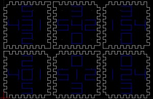
The single cube structure looks like the following:
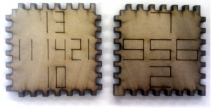
I’ve also added one more feature I haven’t talked about yet: the numbers. They’re not actually strictly needed, and you can still make structures with the numbers removed, but they do make life quite a lot easier, as they tell you how to put the structure together. Each face has 5 numbers on it – a centre number indicating which face this is, and 4 others (one per edge) indicating which other face should be joined to this edge. For single-cube structures, you can live without it and figure out the right combinations for yourself, but for anything more complex they’re a life-saver.
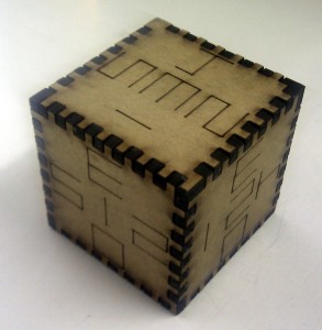
Ok, let’s fire up the laser! I’ve only made two things with this so far, and the first was the single-cube structure. In this particular case, I set the numbers to be on the outside because it’s helpful in explaining to people about the system, but in general the numbers are usually on the inside of a structure. They’re done using similar cutting settings, but a much faster speed so that the laser only just grazes the surface rather than cutting all the way though.
I was somewhat impressed this actually worked. There’s a big gap between looking at something on a computer, and actually physically building it (and in fact the first iteration of this failed because I set the cutting settings wrong on the laser), and it’s a very nice thing to have the end result in your hands.
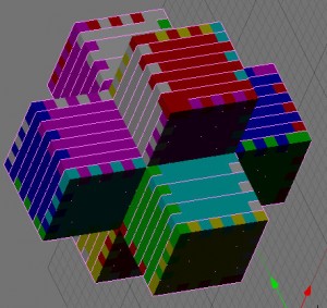
So, let’s try something a bit harder. My next item was a “inverted level-1 Menger sponge” as I thought of it, but it tends to be thought of as a 3-d cross. Here’s what I’m aiming for:
This is a notably more complex structure, because it needs the internal face culling; it’s got 30 faces to the cube’s 6; it contains 8 of the 6-owner unit cubes mentioned earlier; and also because it can’t really be assembled in one go. Instead, I assembled the 6 5-face cubes that it’s made of, and then put them together.
Here’s what a couple of the faces look like to start with:
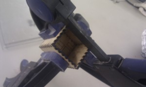
Here’s one of the cubes waiting for the wood glue to dry while I assemble some of the others (the F-clamps are there to get a tighter fit of the pieces):
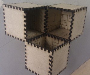
I then glued 3 of the cubes together (see also the numbers inside them)
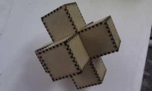
And then we have the finished product! For the curious, this is about 15cm across.
It’s been a very fun experience, and I’d recommend it to anyone who gets the chance. Next plans include possibly doing this in several colours of acrylic, or maybe making bigger items (this last one took about 2 hours to assemble, so that’ll put me off making anything much bigger). Also, if I did this in acrylic I’d have to consider the cut width. Right now, the software assumes a zero cut-width, and I’m getting away with this because of the relative softness of MDF and some carefully applied brute force.
